In this tutorial, different capacitance measurements of a 1N4004 diode are taken in reverse polarization,
for different widths of the depletion region of the PN junction.
IMPORTANT:
The diode MUST NOT BE polarized in direct polarization (conduction mode).
The tutorial consits in four measurement proceses. In the first measure,
the diode is polarized with a voltage corresponding to the weak depletion region
(polarization below the threshold voltage of the diode).
The three following processes correspond to successive reverse polarizations,
in order to obtain the variation of the capacitance in the junction.
The diode is supposed has been connected to the equipment as is shown in the following
figure:
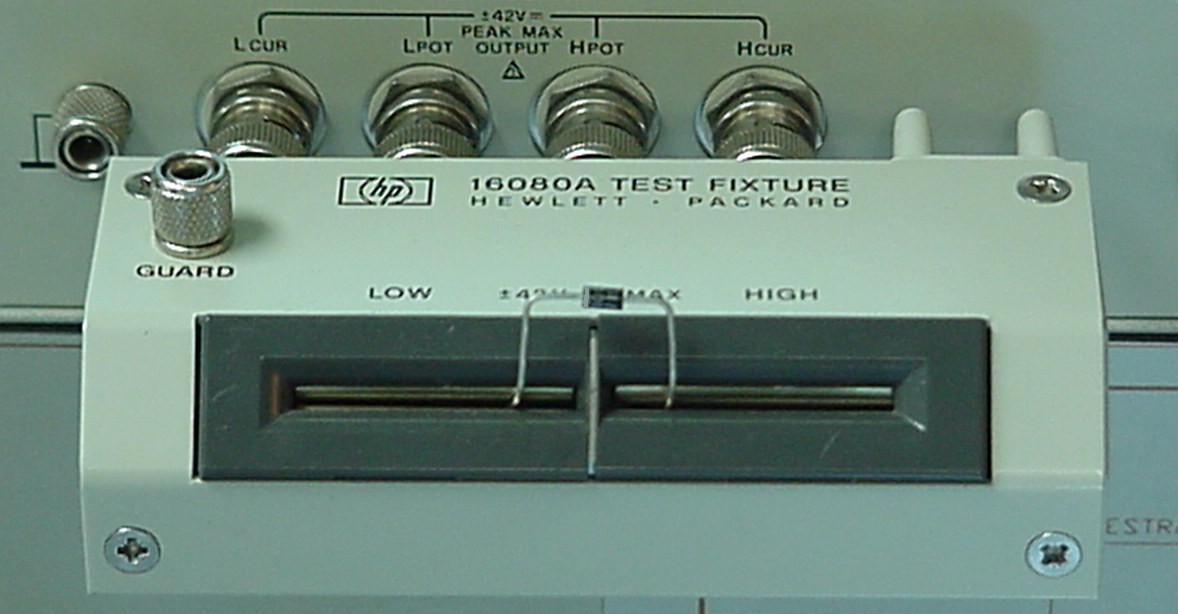
where the diode´s anode has been connected to the HIGH terminal.
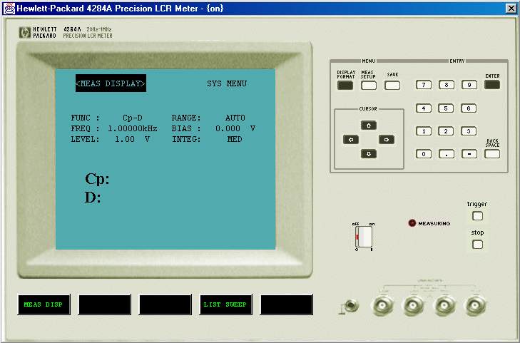
To start the measurements, press the buttom ON to switch-on the
equipment. Initially, the equipment shows the screen <MEAS DISPLAY>.
Real Photo (116 KBytes)
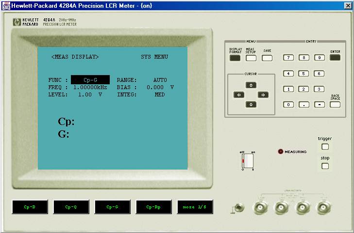
With the cursor keys, select the type of measurent to be accomplished,
in this case Cp - G, Capacity - Conductance:
Real Photo
(113 KBytes)
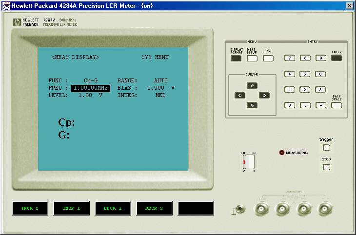
The next step is to select the measurement frequency, that will be equal to 1MHz in this case,
introducing the value (1) through the numeric keyboard and pressing the MHz softkey.
Real Photo;
(111 KBytes)
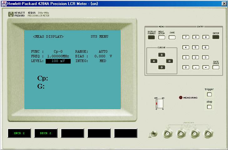
In the next step, it is possible to select the measurent signal amplitude. We select a value of 100 mV,
with a similar process to the frequency seleccion (keyboard-softkey).
Real Photo
(115 KBytes)
the RANGE parameter must be in AUTO mode ( by default).
The Next step is to select the polarization voltage (BIAS), beginning with
a value of 0.2 volts, corresponding to weak depletion.
(This polarization voltage must be always below the threshold voltage of the diode).
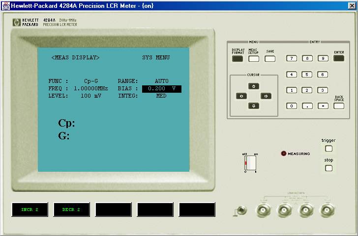
Real Photo (97 KBytes)
In the screen it will be shown the value of the measured capacitance, 36.85 pF in this case.
Next steps consist on repeat the previous process, using the different values of the BIAS Voltage:
| Weak Depletion |
0 Vols |
| Depletion |
-0.2 Volts |
| Depletion |
-0.5 Volts |
| Strong Depletion |
-1.0 Volts |
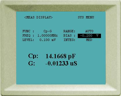
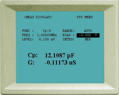
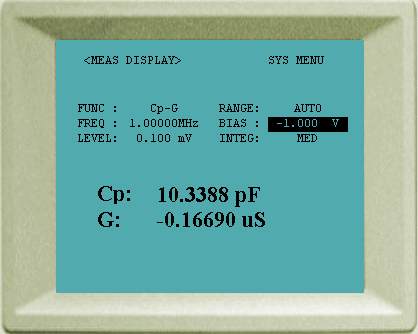
The values of the measured capacitances are shown in the following
figures:
The capacitance values obtained for the different regions, for this device, were:
|
BIAS (volts) |
Capacitance (picofarads) |
| direct (BIAS<VThreshold) |
+0.2 |
36.85 |
| weal depletion |
0.0 |
17.00 |
| depletion |
-0.2 |
14.17 |
| depletion |
-0.5 |
12.11 |
| strong depletion |
-1.0 |
10.34 |