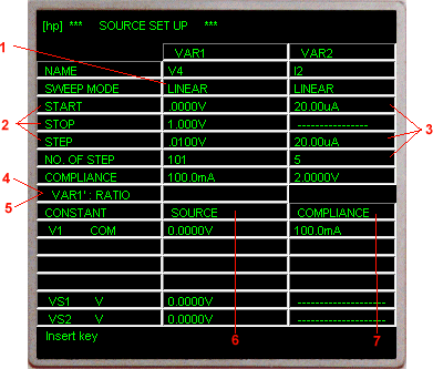

1. Select the sweep mode (linear or log) for the VAR1 source channel. 2. Set the START, STOP, and STEP values for the VAR1 source channel. 3. Set the START, STEP values and NO. OF STEP for the VAR2 source channel. 4. Set the RATIO and OFFSET values for the VAR1’ source channel. 5. Set the HOLD TIME and DELAY TIME. 6. Set the source (output) value for the CONST channels. 7. Set the COMPLIANCE value for each source channel. |
To change or enter source channel parameters on this page,move the cursor to the desired field and enter the parameter value with the DATA ENTRY keys of the front panel or computer keyboard.
Each time an entry is made the cursor automatically move to the next field.
Except for SWEEP MODE, only numeric values and engineering units (m, u, n, p) can be entered on this page.
The source name assigned to each source channel on the CHANNEL DEFINITION PAGE is automatically entered on this page.
When entering numeric values on this page, it is not necessary to enter the value unit. The unit for voltage values is V (volt); for current values, A (ampere); and for time values, s (seconds). When the ENTER key is pressed the unit will be automatically entered. Voltage and current limits for the SMUs and voltage sources (Vs) are listed below:
SMU Voltage Range 0 to ±100V Current Range 0 to ±100mA Vs Voltage Range 0 to ±20V
Values are entered in fixed decimal format.
SWEEP MODE can be selected only with the softkeys and when the cursor is in the SWEEP MODE row of the VAR1 column.
LINEAR: Linear staircase sweep at the specified STEP value.
LOG 10, LOG 25 and LOG 50: Logarithmic staircase sweep at 10, 25, or 50 measurements per decade.
START and STOP determine the sweep range for the VAR1 source channel. START value can be less than, equal to, or greater than the STOP value. If LOG has been selected as the SWEEP MODE, START and STOP must have the same signs. If the specified START and STOP values are identical, no sweep is performed and measurement is made at one point only. STEP determines the number of measurement points for LINEAR sweep. If LOG has been selected as the SWEEP MODE, the instrument automatically calculates and enters the appropiate STEP value. In LINEAR SWEEP MODE, if the STEP value is greater than the START/STOP range (STEP>|STOP-START|), no sweep is performed and measurement is made at the START value only. NO. OF STEP (number of steps) for VAR1 is automatically calculated by the instrument as| STOP-START |
The START, STOP, and STEP values must be such that NO. OF STEP does not exceed 1024. Also, both the START and STOP values for LOG sweep must be grater than zero. Even if zero is entered, it is automatically changed to 1mV or 1pA.
START, STEP, and NO. OF STEP (number of steps) determine the sweep range for the VAR2 source channel. VAR2 sweeps are VAR1 dependent; that is, VAR2 is swept one STEP for each complete sweep of VAR1. The maximum NO. OF STEP for VAR2 is 32. When only one monitor channel (SMU or Vm) is used the maximum number of measurement point is
If the number of measurement points exceeds 1140, the instrument returns the first 1140 measurement values.
VAR1’ con be swept in unison with VAR1 at a constant RATIO or OFFSET. The output from the VAR1’ source channel is calculated as
To enter RATIO and OFFSET, move the cursor to START, STOP, STEP, or COMPLIANCE of VAR1 column, press the VAR1’ RATIO or VAR1’ OFFSET softkey, enter the desired value, and press ENTER. Both RATIO and OFFSET can be entered, but only the one displayed on this page is valid during measurement.
The specified RATIO or OFFSET values must be such that the VAR1’ source channel does not exceed its maximum output (SMU, ±100V; Vs, ±20V).
For log sweep measurements, only VAR1’ RATIO can be specified.
HOLD TIME is the initial wait time and the wait time after a VAR2 step change. DELAY TIME is the wait time after VAR1 step change.
To enter HOLD TIME and DELAY TIME, move the cursor to START, STOP, STEP, or COMPLIANCE of VAR1 column, press the HOLD TIME or DELAY TIME softkey, enter the desired value, and press ENTER. Both HOLD TIME and DELAY TIME can be entered,
The NAME and SOURCE MODE of all source channels that were assigned the CONST SOURCE FCTN on the CHANNEL DEFINITION page are listed in the CONSTANT column on this page.
The order in which they are listed is identical to the order on the CHANNEL DEFINITION page.
To enter the SOURCE value, move the cursor to the desired field, enter the value, and press ENTER.
The value for a COM source channel is set to 0V by the instrument and cannot be changed.
COMPLIANCE is a special feature for protecting samples against over-voltage or over-current damage. It limits the current output from a voltage source or the voltage output from the current source.
COMPLIANCE for a COM source is set to 105mA by the instrument, and it cannot be changed.
The COMPLIANCE for a CONSTANT Vs is 10mA but is not displayed on this page.
More information about this topic can be found in COMPLIANCE.