SOURCE AND MEASUREMENT CHANNELS
The 4145b is equipped with eight channels for device stimulus and measurement. Channels 1 through 4 are Source/Monitor units (SMUs), channels 5 and 6 are voltage sources (VS1 and VS2), and channels 7 and 8 are voltage monitors (Vm1 and Vm2). By correctly combining and setting up the source and measurement channels, a wide range of semiconductor devices can be measured.
 SOURCE/MONITOR UNITS (SMU) SOURCE/MONITOR UNITS (SMU)
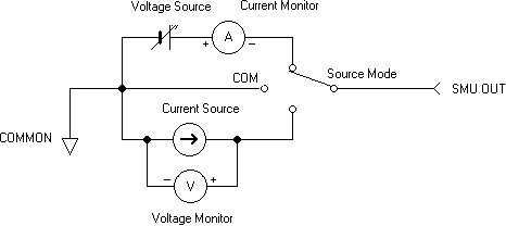
A simplified circuit diagram of one of the four SMUs is illustrated in FIGURE. Each SMU can be set up to function as a voltage source/current monitor, current source/voltage monitor, or source common by specifying source mode V, I, or COM, respectively, in the SOURCE MODE field on the CHANNEL DEFINITION PAGE. Output voltage (SOURCE MODE V) and output current (SOURCE MODE I) can be held constant or can be swept (linearly or logarithmically) by specifying source function CONST or VAR1, VAR1’, VAR2, respectively, in the SOURCE FCNT field on the CHANNEL DEFINITION page. When the source mode is COM, source function is automatically set to CONST.
Output voltage and current, sweep mode (linear or log), START, STOP, STEP, and COMPLIANCE for each SMU are specified on the SOURCE SETUP PAGE.

 VOLTAGE SOURCES (Vs) and VOLTAGE MONITORS (Vm) VOLTAGE SOURCES (Vs) and VOLTAGE MONITORS (Vm)
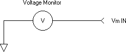
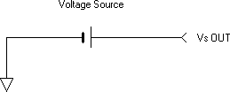
Simplified circuit diagrams of the voltage sources (Vs) and the voltage monitors (Vm) are shown in FIGURES. Output voltage from each Vs can be held constant or can be swept (linearly or logarithmically) by specifying source function CONST or VAR1, VAR1’, VAR2, respectively, in the SOURCE FUNCTION field on the CHANNEL DEFINITION PAGE. Maximum output voltage is ±20V with 1mV resolution.
Up to ±20V can be measured by the voltage monitors.
 
COMPLIANCE
To prevent over-voltage or over-current damage to the device under test, several levels of output protection, termed COMPLIANCE, have been incorporated into the 4145b. The maximum output current from an SMU operating in SOURCE MODE V (voltage source/current monitor) can be specified by entering the desired limit in the COMPLIANCE filed of each source channel on the SOURCE SETUP PAGE. Similarly, the maximum output voltage from an SMU operating in SOURCE MODE I (current source/voltage monitor) can be specified. Maximum specifiable compliance depends on the voltage or current range at which the source channel is operating,

When an SMU is operating in SOURCE MODE COM, its current compliance is automatically set to 105mA and cannot be changed.
If a source channel reaches compliance during measurement, an error code will appear on the display. Measurement data obtained prior to this point is valid, but measurement data obtained after compliance is reached may not be valid. The reason for this is that once a source channel reaches compliance, it tends to act as a constant source. Consider for example, an SMU that is set to SOURCE MODE V (voltage source/current monitor) and SOURCE FCNT VAR1 (variable voltage source). START voltage, STOP voltage, and compliance are 0V, +20V, and 10mA, respectively. Also, assume that the device under test has a resistance of 1000 ohms. When the measurement
is started, the SMU will be begin sweeping its output voltage toward +20V. But when the output voltage reaches +10V, the current through the device under test is 10mA. Compliance has been reached. The SMU will continue to try to sweep toward the +20V STOP voltage, but because the current through the device under test is now constant at 10mA, the voltage across it must
be constant at +10V.
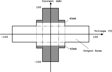
The specified compliance is valid for positive and negative values, regardless of the polarity specified in the COMPLIANCE field; that is, specifying a current compliance of 40mA, is valid for +40mA and –40mA. Output currents greater than ±40mA are not possible.
SWEEP MEASUREMENT
Output from the SMUs and voltage sources (Vs) can be swept in a staircase manner, by specifying VAR1, VAR1’, or VAR2 in the SOURCE FCNT field on the CHANNEL DEFINITION PAGE. The maximum number of source channels that can be swept is three. VAR1, VAR1’, and VAR2 can be specified only once on the CHANNEL DEFINITION page and VAR1’ cannot be specified without VAR1.
Sweep setup is made on the SOURCE SETUP PAGE by selecting the SWEEP MODE and entering the desired START, STOP, STEP, DELAY, and HOLD values. Each sweep parameter is described below:
 START: Voltage or current value at which sweep begins. START: Voltage or current value at which sweep begins.
 STOP: Voltage or current value at which sweeps stops. STOP: Voltage or current value at which sweeps stops.
 STEP: Sweep incremental or decremental value. Can be specified in LINEAR SWEEP MODE only. STEP: Sweep incremental or decremental value. Can be specified in LINEAR SWEEP MODE only.
 DELAY: Wait time before measurement is made at each step (softkey function). DELAY: Wait time before measurement is made at each step (softkey function).
 HOLD: Wait time before sweep begins (softkey function). HOLD: Wait time before sweep begins (softkey function).
 SWEEP MODE: LINEAR or LOG. In LINEAR mode, output is swept linearly in accordance with the specified STEP value. In LOG mode, output is swept logarithmically
at 10 steps, 25 steps or 50 steps (selectable with softkeys) per decade. LOG cannot be specified for VAR2. SWEEP MODE: LINEAR or LOG. In LINEAR mode, output is swept linearly in accordance with the specified STEP value. In LOG mode, output is swept logarithmically
at 10 steps, 25 steps or 50 steps (selectable with softkeys) per decade. LOG cannot be specified for VAR2.
The above sweep parameters are for VAR1 only. Sweep parameters available for VAR2 are START, STEP, and NO. OF STEPS.
Sweep parameters available for VAR1’ are OFFSET (specifiable in linear sweep mode only) and RATIO, both of which are softkeys functions.
Of the six source channels (four SMUs, two voltage sources), three can be swept by specifying VAR1, VAR1’, or VAR2 in the SOURCE FCNT field on the CHANNEL DEFINITION PAGE. The remaining three source channels are either "not used" or are set to CONST source function. The VAR1 source channel is the main sweep channel and VAR2 and VAR1’ are VAR1 dependent, and as described below:
 VAR2 (subordinate sweep): VAR2 (subordinate sweep):
At the completion of the VAR1 sweep, VAR2 is incremented or decremented by the specified STEP value and VAR1 is swept again. The total number of VAR1 sweeps is determined by the NO. OF STEPS specified for VAR2. VAR2 cannot be swept logarithmically. Also, VAR1 and VAR2 can have different source functions. START, STEP, and NO. OF STEPS must be specified.

 VAR1’ (synchronous sweep): VAR1’ (synchronous sweep):
VAR1’ can be used only when VAR1 is used and it must have then same source mode (V or I) as that specified for VAR1. VAR1’ is swept in synchronism with VAR1 at either a constant offset value or constant ratio. VAR1’ offset and ratio values are entered with the corresponding softkey. The offset value and ratio must be such that the VAR1’ source channel does not exceed
its maximum output limits.
The number of measurement points per decade in LOG sweep is selectable at 10, 15, or 50. The output at each point is determined by the number of measurement points per decade and the sweep START value.
INTEGRATION TIME
To prevent line frequency noise and another noise sources from affecting the accuracy of measurements, the 4145b is equipped with three igital integration times, which are selectable from the front panel. Each is described below:
 SHORT: Digital integration is not performed. SHORT: Digital integration is not performed.
 MEDIUM: Measurement result is the average value of 16 samples taken during one line frequency periods. MEDIUM: Measurement result is the average value of 16 samples taken during one line frequency periods.
 LONG: Measurement result is the average value of 256 samples taken during sixteen line frequency periods. LONG: Measurement result is the average value of 256 samples taken during sixteen line frequency periods.
|


